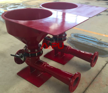
Let's take common hopper of 6" as example and explain the basic principle. The drilling fluids enter the unit via a 6-in. (DN150) line, and the nozzle constricts the flow to a 1.75- in. (45-mm) orifice in the nozzle via a downstream, inwardly sloping conical shape. The flow exits the downstream side of the nozzle at high velocity into a void space. The mixing hopper or other flowline opens into this void space via a manual butterfly valve. With the valve open, the high-velocity flow creates a zone of relative low pressure, which creates suction, drawing the material into the void space.
The powdered material drawn into the void space is then carried by the high-velocity flow into the mouth of the diffuser where the geometry promotes turbulence and thus mixing. Flow moves through the throat of the diffuser into a secondary void space, which again changes velocity, creating more turbulence and recirculation zones. The flow then enters the second throat of the diffuser and exits into the 6-in. (152-mm) pipe which again changes the flow velocity creating more recirculation and turbulence and further encouraging mixing. At this stage, all material is effectively entrained in the fluid
The proprietary eductor design minimizes pressure loss, provides consistently higher vacuum, requires less energy, maintains a rapid rate of induction and reduces “fish eyes.” The ability to maintain high productivity under consistently low or variable circulating pump pressures makes the hopper unit the leader in rapid mixing technology
During operation, we can configure centrifugal pump together with hopper on one skid or we set hopper and pump separately on tank top and tank skid. Please contact us for further doubt, we're happy to solve your questions