How Mud Cleaner Works in Drilling Operations
The Two-Stage Separation Mechanism
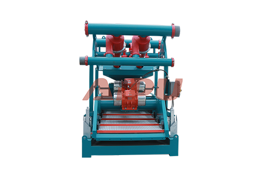
A mud cleaner operates through a sequential, two-stage process that separates particles first by mass/density, then by size.
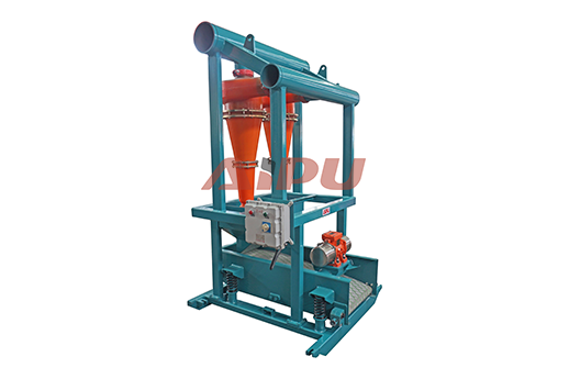
Stage 1: Hydrocyclonic Separation - The Mass Classifier
Feed & Pressurization:
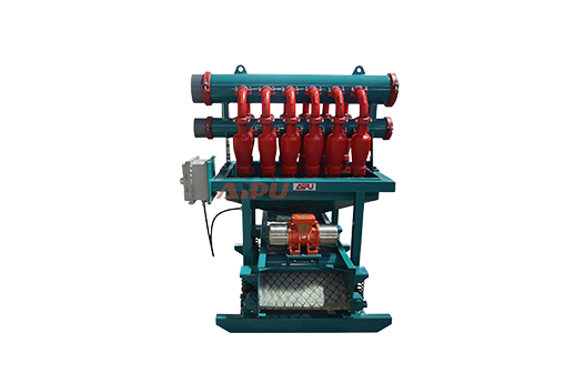
Weighted drilling fluid from the active system is pumped into the mud cleaner unit at approximately 0.35-0.5 MPa (50-75 psi). This pressurized feed enters a manifold distributing fluid to multiple 4-inch hydrocyclones (typically 8-16 cones arranged in parallel).
Centrifugal Action:
As the slurry enters each cone tangentially, it creates a rapid vortex. The resulting centrifugal force (hundreds of times greater than gravity) throws particles outward against the cone wall. Separation occurs primarily by mass:
-
Heavy/Large Particles: Experience greater force, migrate downward along the cone wall, and exit through the apex (bottom opening) as a concentrated slurry called "underflow." This contains BOTH barite and drilled solids.
-
Lighter/Smaller Particles: Remain in the central upward spiral and exit through the vortex finder (top opening) as "overflow," returning to the active system.
Key Point: At this stage, valuable barite and undesirable drilled cuttings travel together out the bottom—this is why standalone hydrocyclones cannot be used on weighted mud.
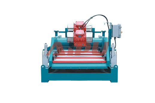
Stage 2: Vibratory Screening - The Size Selector
Underflow Distribution:
The dense slurry from all hydrocyclone apexes converges onto a single fine-mesh vibrating screen (typically 150-200 mesh, with openings of 74-100 microns).
The Critical Separation:
The screen performs the decisive "keep or discard" judgment based strictly on particle size:
-
Passing Through (Keep): Particles smaller than screen openings—including virtually all barite (ground to 1-74 microns) and remaining fluid—fall through the screen. These are returned to the active mud system, preserving the mud's weight and chemistry.
-
Retained on Screen (Discard): Particles larger than screen openings—primarily abrasive drilled solids in the 40-100 micron silt range—are retained. The screen's vibratory motion conveys these solids to the discharge end, where they are discarded as waste.
Visualizing the Process: A Step-by-Step Workflow
[DRILLING FLOW]
     ↓
Weighted Mud (Barite + Drilled Solids + Fluid)
     ↓
[STAGE 1: HYDROCYCLONE BANK]
     ├── OVERFLOW → Cleaner Fluid → Returns to Active System
     └── UNDERFLOW → Barite + Solids Slurry
                            ↓
                    [STAGE 2: FINE-MESH SHAKER]
                            ├── THROUGHPUT → Barite + Fluid → Returns to Active System
                            └── REJECTS → Drilled Solids Only → Discarded as Waste
Key Operational Parameters & Controls
For optimal performance, drillers monitor and adjust:
-
Feed Pressure: Maintained at 50-75 psi for proper hydrocyclone vortex formation
-
Apex Discharge: Adjusted to achieve a "rope" or "spray" discharge indicating proper separation
-
Screen Mesh Selection: Balanced between barite recovery (finer mesh) and screen life/flow rate (coarser mesh)
-
Feed Density: Consistent density ensures stable separation efficiency
Practical Implications on the Rig Floor
When Drillers Observe: Increased viscosity, rising solids content, or decreasing ROP (Rate of Penetration), they activate or optimize the mud cleaner to:
-
Remove abrasive solids damaging pump parts
-
Reduce torque and drag caused by fine solids
-
Maintain fluid properties within specification
-
Lower mechanical friction and equipment wear
Economic Impact: A properly functioning mud cleaner typically pays for itself within days through barite savings alone, while simultaneously reducing waste disposal costs by producing drier cuttings.
Distinguishing from Other Equipment
-
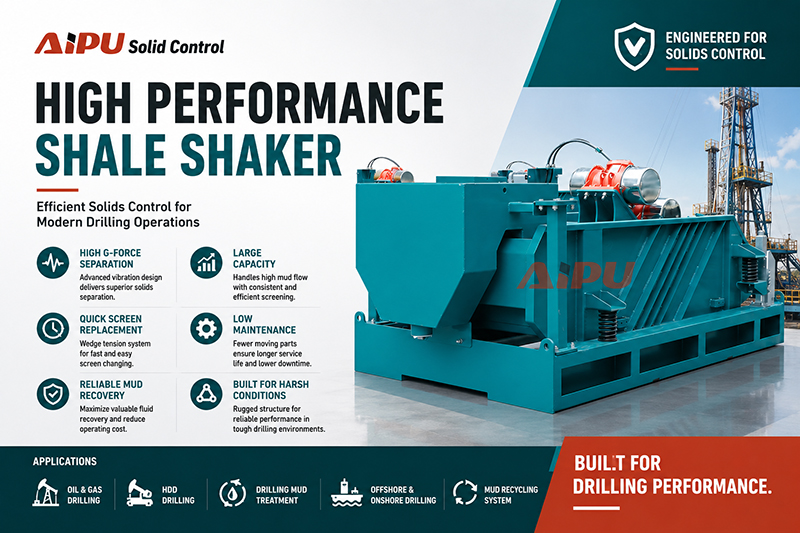
Vs. Shale Shaker: Uses screens only; cannot separate barite from similarly-sized cuttings
-
Vs. Desander/Desilter: Uses hydrocyclones only; would discard barite with cuttings
-
Vs. Centrifuge: Separates by mass differential; excellent for final polishing but with higher cost and complexity
Conclusion: Precision Engineering for Practical Solutions
The mud cleaner works not through a single revolutionary technology, but through the intelligent sequencing of two established separation methods. By first grouping particles by mass (where barite and cuttings behave similarly) and then separating them by size (where their manufactured differences become apparent), it solves what would otherwise be an economically prohibitive problem. This elegant solution exemplifies the practical engineering that enables efficient, cost-effective drilling with weighted fluids, directly contributing to faster, safer, and more economical well construction. Its operation, though mechanically straightforward, represents a critical understanding of the physical properties of drilling materials and their impact on the entire drilling process.
Related Products