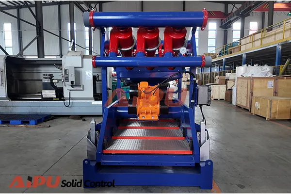
Mud Cleaner: Structure and Components
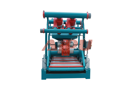
A mud cleaner is an integrated piece of solids control equipment that combines hydrocyclones and a fine-mesh vibrating screen onto a single skid or frame. Its design is optimized for processing the underflow from desanders and desilters to recover liquid and weight material while discharging dry, fine solids.
Here is a detailed breakdown of its core structure and components:
1. Primary Structural Frame (Skid)
-
Function: Provides the rigid, structural base that supports and aligns all components. It is designed for easy transport, installation, and integration into the rig's mud system.
-
Features: Typically a welded steel frame with lifting points (lifting eyes), fork pockets, and often a walkway/guardrail system for operator safety.
2. Feed/Header Box (Distribution Manifold)
-
Function: Receives the slurry (the underflow from upstream hydrocyclones) and evenly distributes it across the width of the vibrating screen(s). This ensures optimal screen utilization and processing efficiency.
-
Structure: A tank or box with internal baffles to manage flow and prevent channeling.
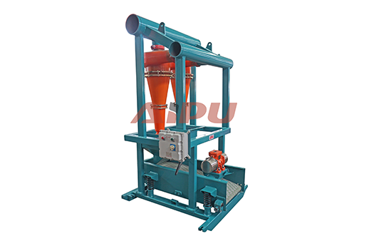
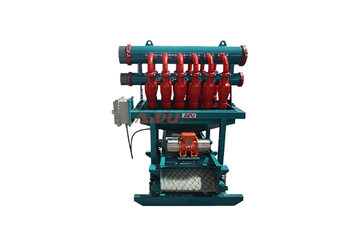
3. Hydrocyclone Section (The "Cleaner" Unit)
This is the core separation module, usually comprising a bank of small-diameter hydrocyclones.
-
Hydrocyclones (Cones): Typically 4-inch or 5-inch diameter cones, arranged in a manifold (often called a "cluster"). Each cone is a conical-shaped vessel with no moving parts.
-
Feed Inlet: Tangential entry point where the pressurized slurry enters, creating a rapid swirling vortex.
-
Cone Body: Where centrifugal force separates heavier solids to the outer wall.
-
Vortex Finder: The central, protruding outlet at the top where the cleaned liquid (overflow) exits and is routed back to the active mud system.
-
Apex (Underflow Nozzle): The adjustable small opening at the bottom tip. It discharges the separated fine solids in a concentrated wet stream (the "underflow") onto the screen below. The apex size can often be adjusted to optimize the "dryness" of the discharge.
-
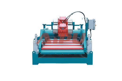
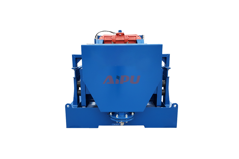
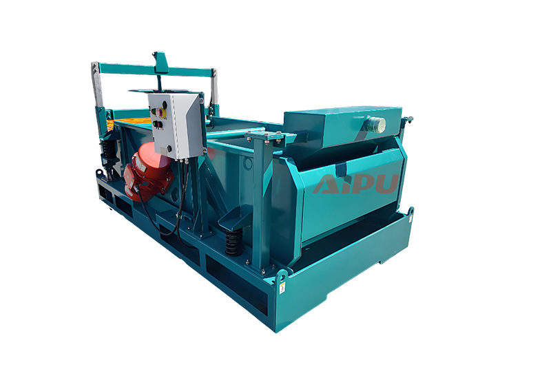
4. Vibrating Shaker Section (The "Screen" Unit)
This section captures the solids from the hydrocyclone underflow.
-
Shaker Deck/Basket: An inclined, vibrating tray that holds the screen panels. It is mounted on isolation springs or rubber mounts.
-
Vibration Motor(s): Usually linear or elliptical motion motors that impart high-frequency vibration to the deck. This action conveys solids off the screen while allowing liquid to pass through.
-
Screen Panels: Fine-mesh screens (commonly 150 to 200 mesh, or 75-100 microns) mounted on the deck. These are the critical consumable components. They allow liquid and barite (weight material) to pass through (becoming "screen throughs" or "effluent") back to the mud tanks, while retaining the fine solids.
-
Discharge Chute (Sand Trap): A chute or collection area at the end of the screen that directs the dried, separated solids (cuttings) away from the unit for disposal.
5. Support Systems & Auxiliary Components
-
Support Stand/Pyramid: For the hydrocyclone cluster, ensuring proper vertical orientation and feeding height.
-
Piping and Valves:
-
Feed Line: Connects from the upstream pump (commonly a dedicated "charge pump") to the header box.
-
Overflow Manifold: Piping that collects the cleaned liquid from all hydrocyclone vortex finders and returns it to the active mud system.
-
Drain Valves: For maintenance and cleaning.
-
-
Electric Motor & Control Panel: Powers the vibration motor(s) and sometimes an integrated feed pump. The control panel allows for start/stop operations.
Schematic Flow of Process (How Components Work Together):
-
Feed: A slurry of mud and fine solids from upstream equipment is pumped into the Header Box.
-
Distribution: The header box distributes the slurry to the Feed Inlets of multiple Hydrocyclones.
-
Centrifugal Separation: Inside each cone, centrifugal force pushes solids outward and downward. Cleaned mud exits via the Vortex Finder (overflow). Solids and a small amount of liquid exit via the Apex (underflow) in a spray pattern.
-
Fine Screening: The underflow sprays directly onto the fine Screen Panels on the Vibrating Shaker Deck.
-
Separation & Recovery: The vibration drives solids up and off the screen to the Discharge Chute. Liquid and valuable barite pass through the screen mesh.
-
Return: The "screen throughs" (liquid + barite) and the hydrocyclone overflow (cleaned mud) are combined and returned to the active mud circulation system.
Key Distinction from Separate Units
The mud cleaner's integrated structure is its defining feature. Unlike separate desilters and a shaker, the mud cleaner's hydrocyclones are mounted directly over its shaker screen, ensuring the underflow is processed immediately without intermediate pooling or piping that can cause clogging. This compact, purpose-built structure makes it highly efficient for its specific role in the middle of the solids control cascade.
Related Products