Mud Cleaner Working Principle: Technical Deep Dive into Hydrocyclone Separation Technology
The mud cleaner represents one of the most sophisticated solid control devices in modern drilling operations, combining the principles of centrifugal separation with fine mesh screening to achieve superior solids removal efficiency. This technical analysis examines the fundamental physics governing mud cleaner operation, the engineering design parameters that influence performance, and the mathematical relationships that determine separation efficiency. Understanding these principles is essential for engineers seeking to optimize solid control systems and maximize drilling fluid performance.
Fundamental Physics of Hydrocyclone Operation
The working principle of a mud cleaner is rooted in fluid dynamics and centrifugal force generation within hydrocyclone cones. When drilling fluid enters a hydrocyclone tangentially at high velocity, typically 15-25 feet per second, it creates a powerful vortex that subjects particles to centrifugal forces hundreds of times greater than gravity. This centrifugal acceleration, expressed in G-forces, can range from 500 to 2000 G depending on hydrocyclone geometry and operating conditions.
- Tangential Velocity: 15-25 ft/s at hydrocyclone inlet creates optimal vortex formation
- Centrifugal Acceleration: 500-2000 G forces separate particles based on density difference
- Vortex Formation: Double vortex structure with outer downward spiral and inner upward spiral
- Residence Time: 0.5-2 seconds for complete particle separation
- Pressure Drop: 30-75 PSI across hydrocyclone drives the separation process
The separation mechanism follows Stokes' Law principles, where the terminal velocity of a particle in the centrifugal field is proportional to the square of the particle diameter, the density difference between the particle and fluid, and the centrifugal acceleration. Particles larger than the cut point migrate to the hydrocyclone wall and exit through the underflow apex, while smaller particles remain in the fluid stream and exit through the overflow vortex finder. The cut point is typically defined as the particle size at which 50% of particles report to underflow and 50% to overflow.
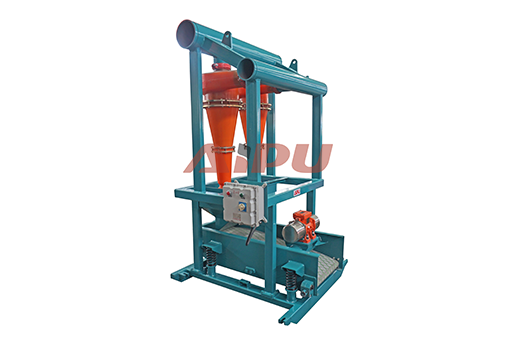
Hydrocyclone Geometry and Design Parameters
The performance characteristics of mud cleaners are fundamentally determined by hydrocyclone geometry, which must be carefully engineered to achieve desired separation efficiency while maintaining acceptable pressure drop and throughput. Key geometric parameters include cone angle, cylinder length, inlet area ratio, and apex diameter. These parameters are interrelated and must be optimized as a system rather than individually.
- Cone Angle: 10-20 degrees for desanders, 15-30 degrees for desilters affects separation sharpness
- Cylinder Length: 1.5-2.5 times cone diameter provides optimal vortex development
- Inlet Area Ratio: 0.05-0.15 of cross-sectional area balances flow and velocity
- Apex Diameter: 0.2-0.4 of vortex finder diameter controls underflow density
- Vortex Finder Diameter: 0.25-0.4 of hydrocyclone diameter determines split ratio
The relationship between hydrocyclone diameter and cut point follows an inverse square relationship: larger diameter hydrocyclones produce coarser cut points, while smaller diameters achieve finer separation. For example, a 6-inch hydrocyclone typically achieves a 74-micron cut point, while a 4-inch unit achieves 44 microns, and a 2-inch unit can separate particles as small as 15-20 microns. This relationship allows engineers to select appropriate hydrocyclone sizes based on the specific solids control requirements of the drilling operation.
Mathematical Modeling of Separation Efficiency
The separation efficiency of mud cleaners can be quantified using several mathematical models that account for particle size distribution, fluid properties, and operating conditions. The grade efficiency curve, which plots recovery percentage versus particle size, provides a comprehensive picture of separation performance. The sharpness of separation, often expressed as the imperfection value (I), indicates how effectively the hydrocyclone separates particles around the cut point.
- Grade Efficiency: Recovery percentage as function of particle size
- Imperfection Value: (d75 - d25) / (2 × d50) where d50 is cut point
- Split Ratio: Underflow to total feed ratio typically 5-15%
- Recovery Efficiency: Mass of target solids recovered / mass in feed
- Capacity Factor: Actual throughput / rated capacity
Theoretical models such as the Bradley model and the Plitt model provide mathematical frameworks for predicting hydrocyclone performance based on design parameters and operating conditions. These models incorporate variables including feed solids concentration, fluid viscosity, particle density, and feed pressure. While these models provide valuable insights, actual performance must be verified through field testing due to the complex interactions between drilling fluid properties and hydrocyclone operation.
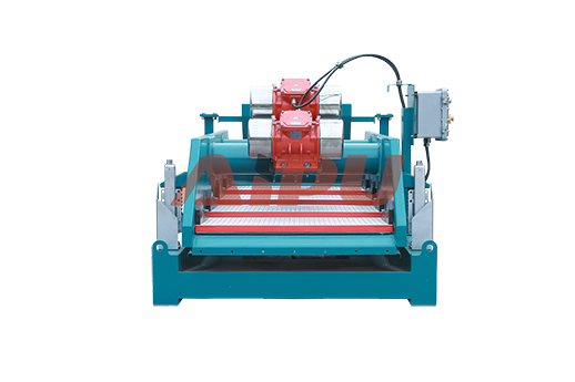
Screen Technology and Secondary Separation
The underflow from hydrocyclones in a mud cleaner passes through fine mesh screens, providing secondary separation that enhances overall system efficiency. Screen selection involves balancing mesh size, wire diameter, and open area to achieve optimal separation while maintaining acceptable flow capacity. Modern mud cleaners often employ pyramid screens or corrugated screens that increase effective screening area and reduce screen blinding.
- Mesh Size: 80-200 mesh determines secondary separation cut point
- Wire Diameter: 0.004-0.008 inches affects screen strength and open area
- Open Area: 30-50% of total screen area determines flow capacity
- Screen Type: Pyramid, corrugated, or flat screens optimize performance
- Screen Life: 200-500 hours depending on abrasiveness of solids
The combination of hydrocyclone and screen separation creates a two-stage process that achieves superior solids removal compared to either technology alone. The hydrocyclone performs bulk separation of coarse and medium solids, while the screen provides fine separation of remaining particles. This staged approach reduces screen loading and extends screen life, while the hydrocyclone underflow concentration prevents excessive fluid loss through the screen.
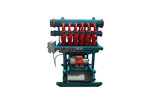
Fluid Dynamics and Flow Distribution
Proper flow distribution across multiple hydrocyclones is critical for achieving consistent separation efficiency in mud cleaner systems. The feed manifold must be designed to provide equal flow and pressure to each hydrocyclone, preventing some units from being overloaded while others operate below capacity. Computational fluid dynamics (CFD) modeling is often employed during the design phase to optimize manifold geometry and ensure uniform flow distribution.
- Manifold Design: Equal flow distribution to all hydrocyclones within ±5%
- Reynolds Number: 10,000-100,000 indicates turbulent flow regime
- Flow Velocity: 8-12 ft/s in feed lines prevents solids settling
- Pressure Balance: Equal pressure at each hydrocyclone inlet
- Pulsation Dampening: Minimizes flow fluctuations affecting separation
The relationship between flow rate and separation efficiency follows a characteristic curve: efficiency increases with flow rate up to an optimum point, after which excessive velocity causes turbulence and reduced separation sharpness. This optimum flow rate typically represents 70-90% of the hydrocyclone's rated capacity. Operating below this range results in insufficient centrifugal force, while operating above causes excessive wear and reduced efficiency.
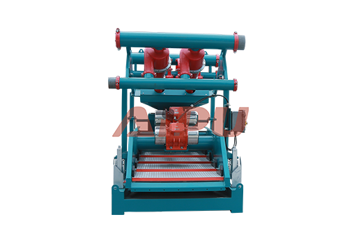
Integration with Solid Control System Architecture
Mud cleaners function as part of an integrated solid control system that includes shale shakers, degassers, centrifuges, and mixing equipment. The positioning of mud cleaners within this system architecture significantly impacts overall performance. Typically, mud cleaners are positioned downstream of primary shale shakers and upstream of decanting centrifuges, creating a graduated separation process that progressively removes solids from coarse to fine.
- System Hierarchy: Shale shakers → Mud cleaners → Centrifuges → Mixing system
- Load Distribution: Each stage removes appropriate solids size range
- Fluid Recovery: Cascading recovery maximizes fluid utilization
- Capacity Matching: Each unit sized for expected solids load
- Bypass Capability: Allows operation during maintenance or low solids conditions
The integration of mud cleaner technology with other solid control equipment requires careful consideration of capacity, pressure requirements, and fluid compatibility. Proper system design ensures that each component operates within its optimal range, maximizing overall efficiency while minimizing energy consumption and wear. Modern solid control systems often incorporate automated controls that adjust flow rates and operating parameters based on real-time monitoring of fluid properties and solids content.
Advanced Materials and Wear Resistance
The abrasive nature of drilling solids necessitates the use of advanced materials in mud cleaner construction to ensure longevity and maintain separation efficiency. Hydrocyclone liners are typically constructed from wear-resistant materials such as polyurethane, ceramic, or rubber compounds, each offering different combinations of wear resistance, impact resistance, and cost. The selection of appropriate materials depends on the specific drilling environment and the characteristics of the solids being processed.
- Polyurethane Liners: Good wear resistance, moderate cost, suitable for most applications
- Ceramic Liners: Superior wear resistance, higher cost, ideal for abrasive conditions
- Rubber Compounds: Excellent impact resistance, lower wear resistance, cost-effective
- Composite Materials: Engineered combinations for specific applications
- Liner Life: 3-12 months depending on material and operating conditions
Wear patterns in hydrocyclones follow predictable trajectories, with the apex area typically experiencing the highest wear rate due to the concentration of coarse solids and high-velocity flow. Regular inspection and replacement of worn liners is essential for maintaining separation efficiency. Advanced mud cleaners may feature replaceable wear inserts or modular construction that allows targeted replacement of worn components without complete unit replacement.
Performance Optimization Strategies
Optimizing mud cleaner performance requires systematic analysis of operating parameters and adjustment based on specific drilling conditions. Key optimization variables include feed pressure, hydrocyclone configuration, screen selection, and flow rate distribution. Performance monitoring should include regular measurement of separation efficiency, fluid properties, and equipment wear to identify opportunities for improvement.
- Pressure Optimization: Adjust feed pressure to achieve target cut point
- Configuration Tuning: Select appropriate hydrocyclone sizes and quantities
- Screen Matching: Choose mesh size based on hydrocyclone underflow characteristics
- Flow Balancing: Ensure equal distribution across all hydrocyclones
- Performance Monitoring: Regular testing and adjustment based on results
Advanced optimization techniques may include computational modeling of separation performance, real-time monitoring of fluid properties, and automated adjustment of operating parameters. The integration of mud cleaners with digital drilling platforms enables data-driven optimization that can significantly improve separation efficiency and reduce operating costs. Continuous improvement programs that track performance over time and correlate with drilling parameters can identify optimal operating strategies for specific applications.
Aipu Solid Control Engineering Excellence
Aipu Solid Control brings 25 years of engineering expertise to mud cleaner design and manufacturing, combining advanced computational modeling with practical field experience to deliver superior performance.
Our commitment to engineering excellence is demonstrated through our ISO 9001 quality management system and compliance with API 13C specifications. Aipu's mud cleaners are designed using advanced materials and manufacturing techniques to maximize wear resistance and minimize maintenance requirements. By choosing Aipu Solid Control, drilling operators benefit from cutting-edge technology backed by decades of engineering expertise and a proven track record of success in the most challenging drilling operations globally.
Related Products