How Does a Mud Agitator Work? The Mechanics of Maintaining Homogeneous Drilling Fluid
In the solids control system, the mud agitator performs a seemingly simple task—stirring the drilling fluid—but the mechanical principles and engineering behind this operation are sophisticated and precisely calibrated. Understanding how a mud agitator works is essential for proper selection, installation, and maintenance to ensure optimal performance throughout drilling operations.
1. The Fundamental Operating Principle
At its core, a mud agitator converts electrical energy into mechanical mixing energy through a straightforward but robust process:
-
Power Input: An electric motor provides rotational energy at relatively high speed (typically 1,450-1,750 rpm depending on power supply frequency).
-
Speed Reduction, Torque Multiplication: A gearbox reduces this high-speed input to a low-speed output (typically 60-72 rpm) while simultaneously multiplying torque. This low-speed, high-torque characteristic is essential for moving viscous drilling fluids and keeping dense solids suspended.
-
Mechanical Transmission: The gearbox drives a vertical shaft that extends down into the mud tank.
-
Fluid Movement: Impellers attached to the shaft rotate within the fluid, creating flow patterns that lift solids from the tank bottom and circulate fluid throughout the tank volume.
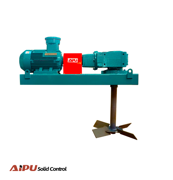
2. Key Mechanical Components and Their Functions
The Drive Motor:
The electric motor provides the prime power source. Based on the APMA series specifications: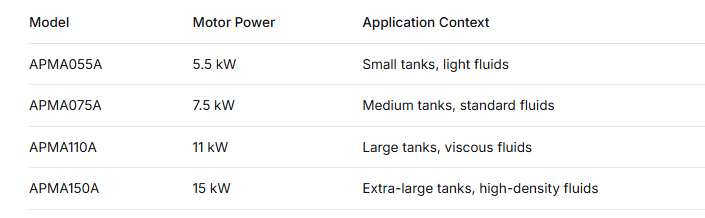
Motors are typically configured for 380V/50Hz or 460V/60Hz power systems, with customization available for other electrical specifications. For hazardous locations, ATEX and IECEX certified motors are available.
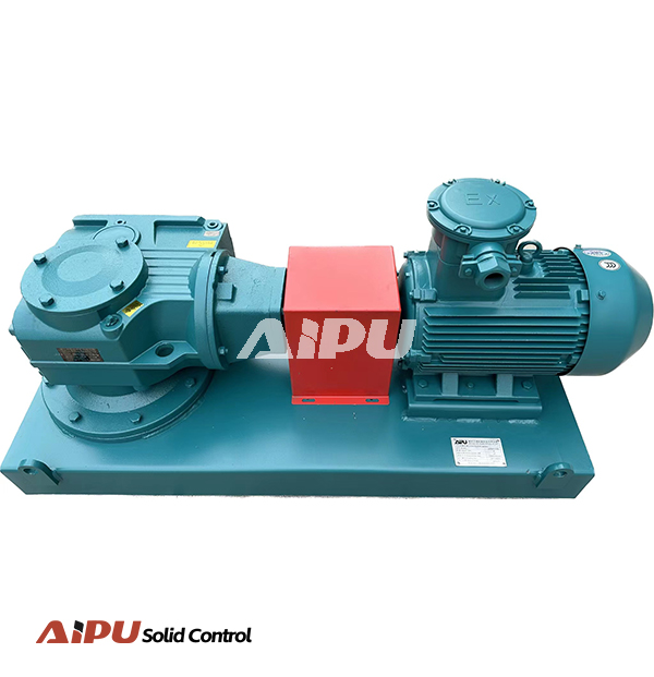
The Gearbox:
The gearbox is the mechanical heart of the agitator, performing two critical functions:
-
Speed Reduction: Reducing motor speed (1,450+ rpm) to impeller speed (60-72 rpm) through a reduction ratio typically 25:1.
-
Torque Amplification: Multiplying motor torque by approximately the reduction ratio, providing the high rotational force needed to move dense, viscous fluids.
Two primary gearbox types are used:
Worm Gear Drives:
-
Construction: A worm (screw) meshes with a worm wheel (gear)
-
Advantages: Compact design, high reduction ratios in a single stage, smooth and quiet operation, self-locking capability prevents back-driving
-
Applications: Standard drilling applications, general-purpose mixing
Bevel Gear Drives:
-
Construction: Straight or spiral bevel gears transfer motion between perpendicular shafts
-
Advantages: Higher efficiency (95-98% vs. 50-90% for worm gears), greater load capacity, longer service life under heavy loads
-
Applications: Demanding conditions, high-viscosity fluids, deep tanks requiring higher torque
The Shaft Assembly:
The shaft transmits rotational power from the gearbox to the impellers:
-
Material: Typically high-strength carbon steel, with optional stainless steel or H2S-resistant materials for corrosive environments
-
Length: Custom-engineered based on tank depth, ensuring the lowest impeller is positioned optimally near the tank bottom
-
Diameter: Calculated to withstand torsional loads without excessive deflection
-
Shaft Stabilizers: For longer shafts, intermediate steady bearings (stabilizers) are installed to prevent shaft whip (vibration) and ensure smooth operation, particularly important in deeper tanks or when processing higher-density fluids
The Impellers:
Impellers are the active mixing elements that actually move the fluid:
Single Impeller Configuration:
-
One impeller mounted at the shaft end
-
Suitable for standard tank depths (typically up to 3-4 meters)
-
Creates a flow pattern that draws fluid from the bottom and circulates upward
Dual Impeller Configuration:
-
Two impellers spaced along the shaft
-
Required for deeper tanks or more viscous fluids
-
Upper impeller diameter typically 800-950 mm (model-dependent)
-
Lower impeller diameter typically 800-950 mm (model-dependent)
-
Creates comprehensive circulation throughout the entire fluid column
Impeller design features:
-
Blade Geometry: Specially angled blades create both axial flow (vertical movement) and radial flow (horizontal dispersion)
-
Diameter: Larger diameters move more fluid but require more power; sizes range from 850-1200 mm for single impellers
-
Material: Abrasion-resistant materials with appropriate coatings for corrosion protection
The Mounting Base:
-
Structural steel frame that supports the entire agitator on the tank top
-
Engineered to distribute dynamic loads and resist vibration
-
Provides access for maintenance while maintaining structural integrity
3. Step-by-Step Operating Sequence
Step 1: Power Application
When the electric motor is energized, it begins rotating at its design speed (typically 1,450 rpm for 50Hz systems, 1,750 rpm for 60Hz systems).
Step 2: Speed Reduction and Torque Multiplication
The motor shaft drives the gearbox input. Through the gear reduction mechanism (worm/gear or bevel gear set), the high-speed, low-torque input is transformed into low-speed, high-torque output. For a 25:1 reduction ratio, a 1,450 rpm motor input becomes approximately 58 rpm at the output shaft, while torque is multiplied by roughly the same factor (minus efficiency losses).
Step 3: Power Transmission Down the Shaft
The gearbox output flange connects to the vertical shaft. The rotating shaft transmits this low-speed, high-torque power downward through the fluid to the impeller(s). Shaft stabilizers, if present, prevent lateral movement and maintain concentric rotation.
Step 4: Impeller Rotation and Fluid Movement
As the impeller rotates within the drilling fluid, several things happen simultaneously:
-
Pressure Differential: The rotating blades create a pressure differential—low pressure on the blade's back side, high pressure on the forward face
-
Fluid Acceleration: Fluid is accelerated by the blade surfaces and thrown outward radially
-
Axial Flow: The blade angle directs flow axially (upward or downward depending on design), creating vertical circulation
-
Turbulent Mixing: The combined radial and axial flows create turbulence that keeps solids suspended and ensures homogeneous mixing
Step 5: Creation of Circulation Patterns
The impeller action establishes continuous circulation patterns throughout the tank:
-
Bottom-to-Top Circulation: Fluid near the bottom is drawn upward, carrying settled or settling solids with it
-
Top-to-Bottom Return: Fluid at the top circulates back toward the bottom, completing the loop
-
Horizontal Dispersion: Radial flow components spread fluid laterally, preventing dead zones in tank corners
Step 6: Continuous Suspension Maintenance
As long as the agitator operates, this circulation continues, preventing solids from settling and maintaining uniform properties throughout the tank volume.
4. Understanding Impeller Flow Patterns
The effectiveness of a mud agitator depends significantly on the flow patterns generated:
Axial Flow (Vertical Circulation):
-
Fluid moves parallel to the shaft axis
-
Creates top-to-bottom turnover of the tank contents
-
Essential for lifting heavy solids from the tank bottom
-
Prevents stratification by density
Radial Flow (Horizontal Dispersion):
-
Fluid moves perpendicular to the shaft axis
-
Spreads fluid laterally across the tank width
-
Prevents dead zones in corners and along tank walls
-
Ensures uniform properties throughout the tank cross-section
In well-designed agitators, the impeller generates a combination of axial and radial flow, creating a comprehensive mixing pattern that:
Combined Flow Pattern:
-
Lifts solids from the bottom
-
Circulates fluid to the top
-
Disperses fluid laterally
-
Returns fluid to the impeller for continuous turnover
5. Dual Impeller Operation
For deeper tanks or more demanding applications, dual impellers provide enhanced performance:
Upper Impeller Function:
-
Typically positioned to create downward flow
-
Pulls fluid from the top region and pushes it downward
-
Prevents surface stagnation and ensures top-to-bottom turnover
Lower Impeller Function:
-
Positioned near the tank bottom
-
Creates upward flow or combined flow pattern
-
Lifts settled solids and maintains bottom suspension
-
Works in coordination with upper impeller for complete circulation
Interaction Between Impellers:
The spacing between impellers is critical—too close and they interfere with each other; too far and dead zones can develop between them. Proper engineering ensures the flow patterns complement rather than conflict.
6. Factors Affecting Agitator Performance
Fluid Viscosity:
Higher viscosity fluids require more power to move and create greater resistance to impeller rotation. The motor and gearbox must be adequately sized for the maximum anticipated viscosity.
Fluid Density:
Denser fluids (higher mud weight) require more torque to maintain adequate circulation. This directly affects gearbox selection and power requirements.
Solids Content and Settling Characteristics:
-
High solids loading increases the mass that must be kept suspended
-
Fast-settling materials (like barite) require more aggressive agitation
-
Particle size distribution affects settling rates and mixing energy needs
Tank Geometry:
-
Depth determines shaft length and whether dual impellers are needed
-
Width and length determine the number of agitators required
-
Tank shape influences flow patterns and potential dead zones
Impeller Submergence:
The impeller must be sufficiently submerged to avoid drawing air into the fluid (vortexing), which could cause foaming and pump cavitation. Minimum submergence depends on impeller diameter and speed.
7. The Relationship Between Speed, Torque, and Mixing Effectiveness
Understanding the torque-speed relationship is key to appreciating agitator design:
High Speed, Low Torque (Motor Output):
-
Characteristic of electric motors
-
Insufficient for direct mixing of viscous fluids
-
Would stall if connected directly to impeller in drilling mud
Low Speed, High Torque (Gearbox Output):
-
What the impeller receives
-
Provides the force needed to move heavy, viscous fluids
-
Maintains rotation even under heavy solids loading
Power Equation:
Power (kW) = Torque (Nm) × Speed (rad/s)
For a given power input, reducing speed increases available torque—this is exactly what the gearbox accomplishes.
8. Integration with Tank Systems
Agitator Spacing:
For optimal coverage, mud agitators are typically installed:
-
One every 3 meters along the tank length
-
One per compartment in partitioned tanks
-
Positioned to ensure flow patterns reach all tank areas
Interaction with Tank Internals:
Agitator placement must consider:
-
Suction lines for downstream equipment
-
Baffles that may be installed to direct flow
-
Mud guns that provide auxiliary agitation
-
Access hatches and maintenance requirements
9. Special Operating Considerations
Startup Under Load:
If solids have settled during shutdown, starting the agitator can be challenging. The gearbox must withstand starting torque significantly higher than running torque. Some installations include features to reduce starting resistance.
Variable Speed Operation:
While most agitators run at fixed speed, variable frequency drives (VFDs) can be used to:
-
Adjust mixing intensity for different fluid conditions
-
Reduce power consumption during low-demand periods
-
Provide soft-start capability to reduce mechanical stress
Continuous vs. Intermittent Operation:
In most drilling operations, agitators run continuously to prevent any solids settling. Intermittent operation risks allowing solids to pack, making restart difficult and potentially damaging equipment.
10. Maintenance Considerations for Continued Proper Function
Understanding how the agitator works helps in maintaining it:
Gearbox Maintenance:
-
Regular oil level checks and changes (per manufacturer specifications)
-
Monitoring for unusual noise or vibration indicating wear
-
Checking seals for leaks
Shaft and Impeller Inspection:
-
Visual inspection for wear, especially on impeller blades
-
Checking shaft straightness and stabilizer condition
-
Ensuring no buildup of material causing imbalance
Mounting Integrity:
-
Checking bolts for tightness
-
Inspecting tank top structure for signs of stress or fatigue
-
Ensuring vibration isolation if installed
Conclusion
A mud agitator works through a elegantly engineered sequence: an electric motor provides high-speed power, a gearbox transforms this into low-speed, high-torque output, a shaft transmits this power into the tank, and impellers convert rotational energy into fluid movement. The resulting circulation patterns—axial flow for vertical turnover and radial flow for horizontal dispersion—keep solids suspended, maintain uniform properties, and eliminate dead zones throughout the tank volume.
This mechanical process, while conceptually simple, requires precise engineering to handle the demanding conditions of drilling fluids—high density, variable viscosity, abrasive solids, and continuous operation. Whether configured with worm gear or bevel gear drives, single or dual impellers, the agitator's work is fundamental to the entire solids control system: ensuring that the fluid reaching downstream equipment and mud pumps has consistent, predictable properties essential for efficient drilling operations.
Related Products