How a Solids Control System Works: Fluid Dynamics, Particle Separation, and System Balance
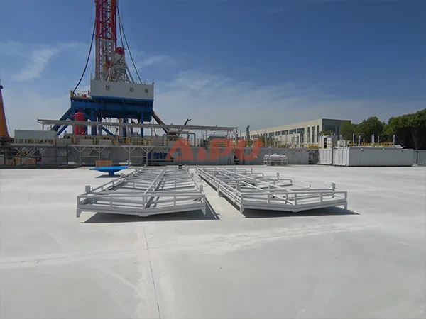
Drilling fluid circulates at high velocity down the drill string, exits through nozzles in the bit, and returns to the surface carrying drilled cuttings. If the solids are not removed, the mud becomes progressively contaminated, leading to reduced penetration rates, stuck pipe, and well control problems. The solids control system is the engineered solution that continuously cleans the mud. But how does it really work, beyond just listing equipment? This article explains the underlying principles of how a solids control system works from the perspectives of fluid dynamics, particle behavior, and system balance. We will use AIPU Solid Control equipment as practical examples.
1. The Essential Function: Restoring Mud Properties
Every drilling fluid has a designed density (specific gravity), viscosity, and filtration control. As the mud circulates downhole, it gains two types of contaminants:
-
Drilled solids – rock cuttings of various sizes.
-
Formation gases – methane, H₂S, CO₂.
The solids control system works by progressively removing these contaminants so that the mud properties are restored before the mud is pumped back downhole. Without this cleaning, the mud would quickly become unusable.
2. The Four Physical Mechanisms of Separation
The system uses four different physical mechanisms, each suited to a particular particle size range.
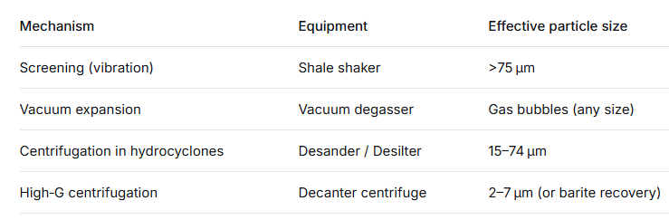
Each mechanism works best within a specific particle size window. By arranging them in descending size order, the system achieves total cleaning efficiency that no single device could match.
3. How Fluid Moves Through the System – The Hydraulic Path
Understanding the flow path is key to understanding how the system works. All components are connected in series, with mud tanks divided into compartments by weir plates.
Step 1 – Return from the well: Mud exits the annulus through a large pipe called the flowline. It enters the first compartment of the mud tank, directly above the shale shaker.
Step 2 – Shaker compartment: Mud falls onto the vibrating screens. Large solids are retained on the screens and discharged. The liquid and fine solids pass through the screen mesh into the compartment below. A weir plate at the opposite end of the compartment allows only liquid (with fine solids) to overflow into the next compartment.
Step 3 – Degasser compartment (if used): A centrifugal pump or gravity feed sends mud to the vacuum degasser. Inside the degasser, gas is removed. Degassed mud returns to the same compartment, then overflows to the next.
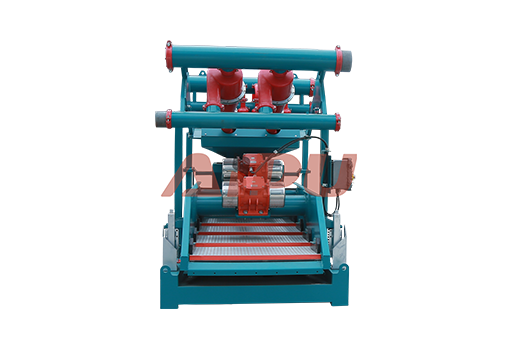
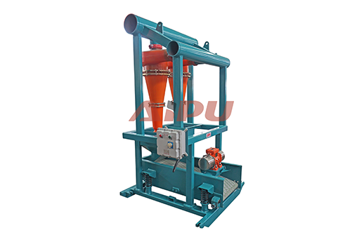
Step 4 – Desander feed compartment: A centrifugal pump draws mud from this compartment and feeds it to the desander hydrocyclones at 0.25–0.45 MPa pressure. The desander’s underflow (sand and water) is discharged; the overflow (cleaner mud) goes to the next compartment.
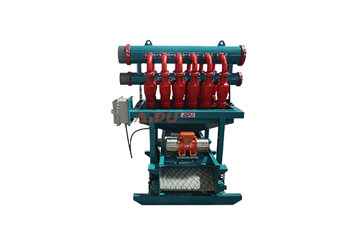
Step 5 – Desilter feed compartment: Another centrifugal pump (or the same, if properly sized) feeds the desilter. The desilter removes finer solids. Its overflow, now mostly free of particles down to 15 µm, flows into the centrifuge feed compartment.
Step 6 – Centrifuge feed compartment: A pump sends mud to the decanter centrifuge. The centrifuge discharges either ultra‑fine solids (unweighted mud) or a barite‑rich stream (weighted mud). The cleaned mud overflows into the suction compartment.
Step 7 – Suction compartment: This is the final compartment. Clean, conditioned mud is stored here, ready for the mud pumps to send back downhole. Agitators run continuously to keep barite and fine solids suspended.
This hydraulic path is continuous. As long as the mud pumps are running, mud flows through the entire system, being cleaned at each stage.
4. How Particle Separation Works at Each Stage – The Science
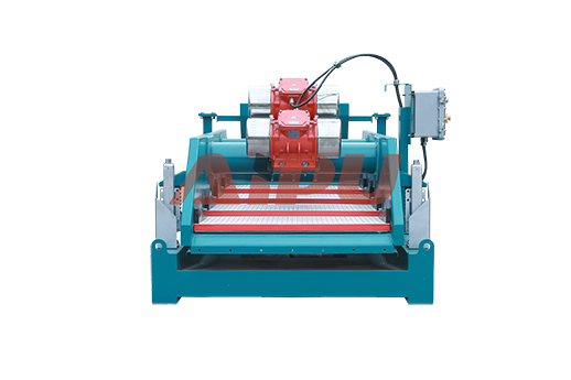
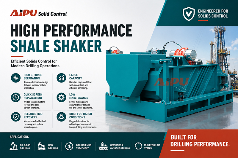
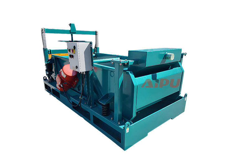
4.1 Shale Shaker – Interception and Stratification
The shaker screen acts as a physical barrier. Particles larger than the screen openings cannot pass. Smaller particles may pass, but the vibration stratifies the bed: liquid and fine particles migrate down through the solids layer. The efficiency of a shaker depends on screen mesh, vibration frequency, amplitude, and deck angle. AIPU Hunter‑MG series shakers allow adjustment of these parameters to match the mud type.
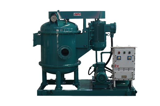
4.2 Vacuum Degasser – Pressure Reduction and Bubble Growth
Gas bubbles are held in the mud by surface tension and viscosity. When the pressure above the mud is reduced to -0.02 to -0.04 MPa, the pressure difference across the bubble wall increases. Bubbles expand, become buoyant, and rise. The vacuum pump continuously removes them. AIPU degassers achieve ≥95% removal efficiency because the thin film created by the rotor ensures that every bubble is exposed to the low pressure.
4.3 Hydrocyclone (Desander / Desilter) – Centrifugal Sedimentation
Inside a hydrocyclone, the tangential feed creates a high‑velocity spiral. The centrifugal force can be 100–200 times gravity. Denser (solid) particles are thrown outward and spiral down to the underflow. Less dense (liquid) spirals up to the overflow. The cut point is controlled by the cone diameter, feed pressure, and apex size. AIPU desanders and desilters use polyurethane cones for wear resistance and consistent performance.
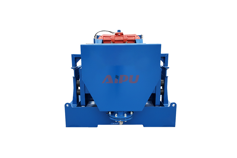
4.4 Decanter Centrifuge – Differential Settling
The centrifuge bowl spins at very high speed (up to 3200 rpm), generating centrifugal forces of 1000–2000 G. Under this force, particles settle according to their size and density. The scroll conveyor moves settled solids to the discharge ports. By adjusting bowl speed and feed rate, the operator can choose to either discard ultra‑fine solids (unweighted mode) or recover barite (weighted mode). AIPU centrifuges are designed for both duties with hardened components.
5. The Concept of Cutting Efficiency and System Balance
A solids control system works properly only when all stages are balanced. If the shaker is too small, large solids bypass into the desander, causing rapid cone wear. If the desander is undersized, fine solids overload the desilter. If the centrifuge is too small, ultrafine solids accumulate and mud viscosity rises.
Balancing rule: Each downstream component must have at least the same hydraulic capacity as the upstream component. AIPU engineers use this rule to size systems: for a rig circulating 200 m³/h, the shaker must handle ≥240 m³/h (1.2x margin), the desander must have enough cones (e.g., two 10″ cones for 240 m³/h), and the centrifuge must handle the desilter overflow (typically 35–65 m³/h).
6. How the System Handles Different Mud Types
Water‑Based Mud (WBM)
All four stages are active. The centrifuge runs in unweighted mode, discarding fine solids to control viscosity. AIPU recommends the APLW355X1257‑N or APLW355X1460‑N (2–5 µm cut point).
Oil‑Based Mud (OBM)
OBM is expensive, so the centrifuge runs in weighted mode to recover barite. A coarser cut point (5–7 µm) is used. The degasser may require H₂S‑resistant steel. AIPU APLW600X1019‑N is suitable for barite recovery.
High‑Gas Wells
The degasser is critical. It must be placed after the shaker and before the desander. For H₂S, AIPU supplies 316L or 2205 duplex steel degassers with sealed vent lines to a flare ignitor.
7. The Role of Mud Tanks in Making the System Work
Mud tanks are not passive. Their internal design—weir plates, sloped bottoms, and agitator placement—directs the flow and provides retention time. Each compartment must be large enough to hold mud for at least 30–60 seconds at the maximum circulation rate. This gives solids time to settle and allows pumps to take suction without starving. AIPU custom designs tanks with computer‑calculated compartments.
8. What Happens When the System Is Not Working Properly
If any stage fails, the consequences are immediate:
-
Shaker screen blinded or bypassed: Large solids enter the desander; cones wear out in days instead of months.
-
Degasser not running: Mud density drops by 0.05–0.10 SG; pump cavitation starts; gas may reach the shaker area, creating a fire hazard.
-
Desander underflow blocked: Sand builds up in the tank, requiring shutdown and cleaning.
-
Centrifuge overloaded: Fine solids accumulate, mud viscosity rises, filtration control worsens.
A properly designed and maintained AIPU system prevents all these problems through balanced sizing and robust construction.
9. Why AIPU Solids Control Systems Are Engineered to Work
AIPU Solid Control has been designing and manufacturing solids control equipment for over 20 years. AIPU systems are in use in more than 30 countries, with over 300 system‑equivalent shipments. Key engineering features that make AIPU systems work reliably:
✅ Matched capacities – Every component is sized to work with the others, avoiding bottlenecks.
✅ Progressive separation – The equipment sequence follows the natural order of particle sizes.
✅ Robust components – Hardened screens, polyurethane cones, stainless steel rotors, and tandem seals.
✅ Corrosion protection – Three‑layer marine coating on tanks and structural parts.
✅ H₂S‑resistant options – 316L/2205 duplex steel for sour gas.
✅ Global certifications – API, HSE, ATEX, IECEX.
10. Conclusion
A solids control system works by processing drilling fluid through a staged series of separation devices that use screening, vacuum expansion, hydrocyclone centrifugation, and high‑G decanting. Each stage removes a specific size range of particles (or gas). The system is balanced so that flow rates match, and the mud tank compartments are designed to provide proper retention and flow direction. When all components work together, the result is clean mud that maintains its properties, protects pumps and downhole tools, reduces costs, and enables safe, efficient drilling.
AIPU Solid Control provides complete, engineered systems that work as intended—from the first shaker to the final centrifuge. Whether you are drilling with water‑based mud, oil‑based mud, or through gas‑bearing formations, AIPU has the right solution.
Trust AIPU to make your solids control system work perfectly.
Related Products