What is a Mud Tank in Drilling? The Foundation of the Surface Fluid System
In the comprehensive architecture of a drilling rig's surface equipment, the mud tank serves as the fundamental infrastructure that supports the entire solids control system and fluid management process. While shale shakers, desanders, centrifuges, and agitators perform specialized separation and mixing functions, the mud tank provides the physical platform where all these activities occur. Understanding mud tanks is essential for grasping how the various components of solids control integrate into a functioning whole.
1. Definition and Core Function
A mud tank, also called a mud pit or reserve pit, is a specially engineered container designed to hold, process, and circulate drilling fluid during drilling operations. More than simple storage vessels, modern mud tanks are sophisticated processing facilities that:
-
Store Drilling Fluid: Maintain sufficient volume of mud for continuous circulation
-
Support Solids Control Equipment: Provide mounting platforms for shakers, degassers, desanders, desilters, and centrifuges
-
Facilitate Fluid Processing: Create controlled flow paths that allow sequential solids removal
-
Enable Chemical Treatment: Provide locations for adding and mixing chemical additives
-
Allow Solids Settling: Permit gravity separation when flow is interrupted
-
Provide Suction for Pumps: House the suction lines for mud pumps and other transfer pumps
2. The Central Role in Solids Control
The mud tank is not merely a container but the central organizing element of the entire surface fluid system:
The Processing Cascade:
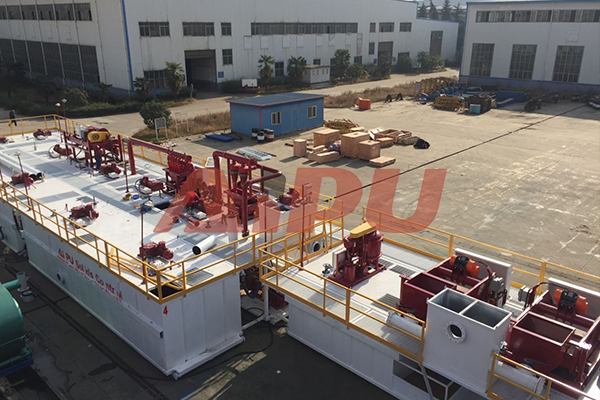
All solids control equipment is arranged sequentially along the tank system:
-
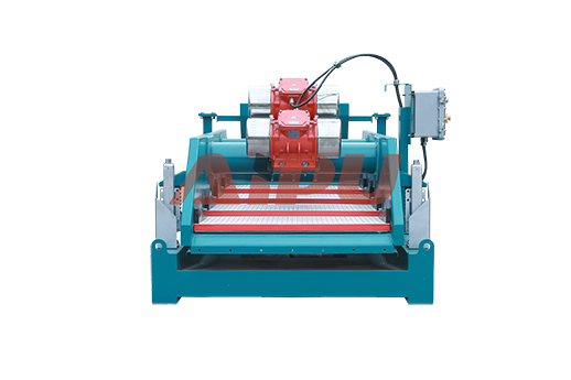
First compartment: Receives returns from the well, equipped with shale shakers for primary separation
-
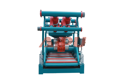
Second compartment: Contains desander for sand-sized particle removal
-
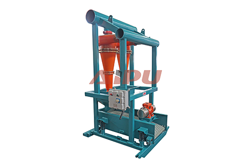
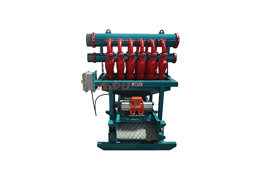
Third compartment: Houses desilter for fine particle removal
-
Subsequent compartments: May contain centrifuges, degassers, and mixing equipment
-
Last compartment: Clean mud suction for mud pumps
Flow Management:
Baffles and weirs between compartments control fluid flow, ensuring:
-
Sufficient residence time for processing
-
Proper distribution to each equipment stage
-
Prevention of short-circuiting (fluid bypassing processing)
-
Controlled liquid levels for equipment operation
3. Key Design Features
Modern mud tanks incorporate numerous engineered features that enhance their functionality:
Tank Bottom Design:
As noted in the brochure, "the standard tank bottom is sloped or V shaped for easy cleaning and less dead corner." This is critical because:
-
Sloped bottoms direct settled solids to sumps or drainage points
-
V-shaped bottoms concentrate solids for easier removal
-
Dead corner elimination prevents accumulation of stagnant solids that could degrade or become difficult to remove
Compartmentalization:
Tanks are divided into multiple compartments, each serving a specific function:
-
Shaker compartment: Receives raw returns, highest solids content
-
Sand trap: Allows initial gravity settling of large particles
-
Processing compartments: Hold desanders, desilters, centrifuges
-
Suction compartment: Cleanest mud, feeds mud pumps
-
Reserve compartment: Stores excess mud for makeup or emergencies
-
Mixing compartment: Area for adding new mud or chemicals
Baffle Systems:
Internal baffles control flow patterns:
-
Weir baffles: Maintain constant liquid levels by allowing overflow at set heights
-
Underflow baffles: Force fluid to flow under barriers, preventing surface shortcuts
-
Perforated baffles: Allow controlled flow while dampening turbulence
Agitator Mounting:
Tanks are structurally reinforced at agitator mounting points to support:
-
Dynamic loads from rotating equipment
-
Vibration transmission
-
Weight of motor and gearbox assemblies
-
Typically requiring one agitator every 3 meters or one per compartment
4. Types of Mud Tanks
Based on the brochure illustrations, several specialized tank configurations exist:
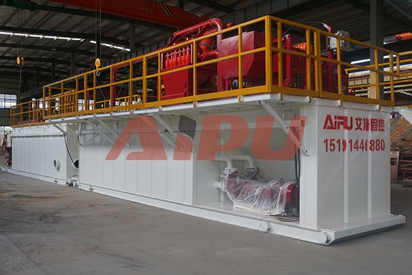
Standard Mud Tanks:
The basic processing tanks that form the main solids control system. Typically rectangular, divided into compartments, with equipment mounted on top.
Transfer Tanks:
Used to move mud between locations—between rigs, from storage to active system, or to disposal sites. Often equipped with:
-
Quick-connect piping
-
Transfer pumps
-
Level indicators
Elevated Fuel Tanks:
Specialized tanks for storing diesel or other fuels, raised to allow gravity feed to engines.
Double-Layer Square Oil Tanks:
For fuel or base oil storage, featuring:
-
Double-wall construction for spill prevention
-
Square design for efficient space utilization
-
Typically used at rig sites for bulk fuel storage
Trailer Mounted Tanks:
Mobile tanks for transport between locations:
-
Mounted on trailers for highway transport
-
Self-contained with necessary connections
-
Used for remote operations or temporary storage
Fracturing Liquid Tanks:
Specialized for hydraulic fracturing operations:
-
High-pressure ratings
-
Large volumes for frac fluid storage
-
Often equipped with manifolds for high-rate transfer
Cement Silos:
Vertical cylindrical tanks for storing dry cement or bentonite:
-
Pneumatic filling and discharge
-
Aeration systems to prevent bridging
-
Weight indicators for inventory control
Cutting Boxes/Mud Skips:
Containers for collecting and transporting drilled cuttings:
-
Sealed to prevent spills during transport
-
Often stackable for efficient shipping
-
May include drainage systems for liquid recovery
5. Construction and Materials
Mud tanks must withstand harsh conditions and are built accordingly:
Materials:
-
Common carbon steel: Standard construction for most applications
-
H2S-resistant steel: For sour service environments where hydrogen sulfide is present
-
Stainless steel: For corrosive environments or special applications
Corrosion Protection:
The brochure specifies "heavy-duty marine anti-corrosion painting with 3 layers" including:
-
Strict sand-blasting procedures before coating application
-
Primer coat: Provides adhesion and initial protection
-
Intermediate coat: Builds thickness and barrier properties
-
Top coat: Resists abrasion, chemicals, and UV exposure
Structural Design:
-
Reinforced for equipment loads
-
Stiffened to prevent flexing during transport
-
Designed with lifting points for crane handling
-
Includes walkways, railings, and access platforms
6. Tank Equipment and Accessories
Modern mud tanks incorporate numerous auxiliary systems:
Mud Guns:
As described in the brochure, mud guns are "mainly used to prevent the mud from being deposited in the mud tank" and "as auxiliary equipment of agitator to stir mud and clean tank bottom." Available in:
-
Low pressure
-
Medium pressure
-
High pressure configurations
Suction Lines:
Piping systems that draw fluid from tanks to pumps:
-
Strategically positioned to avoid drawing settled solids
-
Often include strainers or mud buckets
-
May have multiple pick points for different conditions
Level Indicators:
Various methods to monitor tank volume:
-
Mechanical float systems
-
Ultrasonic sensors
-
Radar level transmitters
-
Simple sight glasses
Agitation Systems:
As previously discussed, agitators mounted on tanks maintain solids suspension. The brochure notes "mud agitator is used in the surface mud tank to suspend solids and maintain a homogeneous mixture throughout the mud solids control system."
Piping Manifolds:
Interconnecting piping allows:
-
Transfer between tanks
-
Bypassing equipment for maintenance
-
Emergency routing
-
Mixing and chemical addition
7. Tank Arrangements and Configurations
Single Tank Systems:
Small rigs may operate with a single compartmentalized tank containing all processing stages in sequence.
Multi-Tank Systems:
Larger operations use multiple interconnected tanks:
-
Active tank system: Main processing tanks for circulating mud
-
Reserve tank: Storage for spare mud
-
Mix tank: Dedicated to preparing new mud
-
Trip tank: Small tank for precisely monitoring fluid levels during trips
-
Waste tank: Collects excess or contaminated mud
Modular Systems:
Modern rigs often use modular tank designs:
-
Individual tank modules that transport separately
-
Quick-connect piping and electrical connections
-
Flexible arrangement for different rig sites
8. Specialized Tank Features
Based on the brochure, several advanced features are available:
Constant Liquid Level Design:
Some tanks incorporate "unique design ensures constant liquid level in the separator and solves the problem of sand accumulation inside the tank."
Buffer Devices:
"Buffer devices are installed at the corners of the liquid supply pipe and replaceable impact resistant baffles are added" to reduce erosion and control flow.
Inspection Capability:
Designs allow that "regular inspection and replacement can be carried out according to wear conditions to extend the service life."
H2S Resistance:
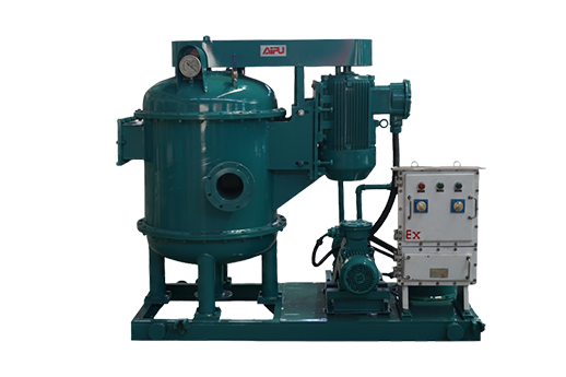
For sour service, "the sulfur resistant mud gas separator is manufactured and processed entirely with special materials, which can completely prevent damage to the equipment caused by hydrogen sulfide in the gas."
9. Tank Maintenance and Cleaning
Proper tank maintenance is essential for system performance:
Cleaning Requirements:
-
Sloped bottoms facilitate cleaning
-
Access hatches allow entry for manual cleaning when needed
-
Some tanks include built-in cleaning systems (mud guns)
Inspection Schedule:
-
Regular inspection of coatings for wear
-
Check baffles and internal structures for erosion
-
Verify level indicator accuracy
-
Test structural integrity
Dead Corner Elimination:
The V-shaped or sloped bottom design "for easy cleaning and less dead corner" prevents accumulation of solids that could:
-
Ferment and produce gas
-
Harbor bacteria
-
Become difficult to remove
-
Affect mud properties
10. Integration with Solids Control Equipment
The tank provides the physical and hydraulic interface for all solids control equipment:
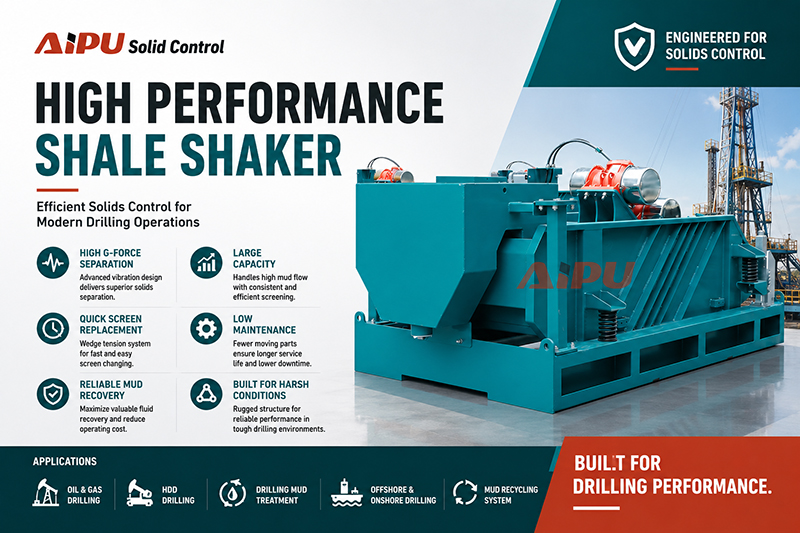
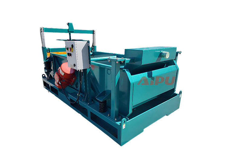
Shale Shakers:
Mounted directly over the first compartment, with discharge into the tank below.
Degassers:
Positioned to receive gas-cut mud and discharge degassed fluid to downstream compartments.
Desanders and Desilters:
Mounted over tanks, with underflow either returning to the tank or going to a bottom shaker.
Centrifuges:
Typically mounted on platforms above tanks, with solids discharge to cuttings boxes and liquid return to the tank.
Centrifugal Pumps:
Mounted at tank level or on platforms, with suction from tanks and discharge to equipment or downstream.
11. Customization Options
The brochure emphasizes flexibility in tank design:
-
Electrical system is customizable for different power requirements
-
Common carbon steel or H2S resistant steel for option depending on service
-
Pressure vessel, inspection certification etc. for specialized applications
-
Surface coating colors for identification or company branding
The mud tank is far more than a simple container—it is the engineered foundation upon which the entire surface fluid system is built. It provides the physical platform for solids control equipment, creates the flow paths that enable sequential processing, stores the fluid volumes necessary for continuous circulation, and integrates all the components into a functioning system.
From the sloped bottoms that prevent solids accumulation to the strategically placed baffles that control flow, from the agitator mounts that maintain suspension to the suction lines that feed mud pumps, every feature of a modern mud tank is designed with a specific purpose. The tank transforms a collection of individual machines—shakers, desanders, centrifuges, pumps—into an integrated processing plant capable of maintaining drilling fluid properties within tight specifications.
In the comprehensive approach to drilling fluid management, the mud tank proves that sometimes the most important equipment is the equipment that holds all the other equipment together.
Related Products