How Does a Jet Mud Mixer Work? The Venturi Principle in Action
The jet mud mixer is one of the most elegantly simple devices in the entire drilling fluid system. Despite its critical role in preparing and weighting drilling mud, it contains no moving parts in the mixing head itself. Instead, it harnesses a fundamental principle of fluid dynamics—the venturi effect—to perform its function. Understanding exactly how this device works is essential for proper operation, troubleshooting, and appreciating the ingenious simplicity of its design.
1. The Fundamental Principle: The Venturi Effect
At the heart of every jet mud mixer lies the venturi principle, first described by Italian physicist Giovanni Battista Venturi in the 18th century.
The Physics Explained:
When a fluid flows through a pipe, it obeys two fundamental laws of physics:
-
Conservation of mass: The same mass of fluid must pass every point in the system per unit time
-
Conservation of energy: The total energy of the fluid (pressure energy + kinetic energy + potential energy) remains constant
When fluid encounters a constriction in the pipe:
-
To maintain mass flow, velocity must increase through the narrower area
-
As velocity increases, kinetic energy increases
-
To conserve total energy, pressure energy must decrease
-
This pressure drop creates a vacuum—lower than atmospheric pressure
This vacuum is the "suction" that draws dry powder into the fluid stream.
2. The Complete Jet Mixer System
Before examining the mixer itself, it's important to understand it operates as part of a complete system:
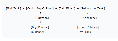
System Components:
-
Centrifugal pump: Provides the high-pressure fluid flow (typically 0.22-0.4 MPa)
-
Suction line: Draws base fluid from the mud tank
-
Jet mixer head: Where the actual mixing occurs
-
Hopper: Holds dry powder material
-
Discharge line: Returns mixed slurry to the tank
-
Tank agitators: Complete the mixing and maintain suspension
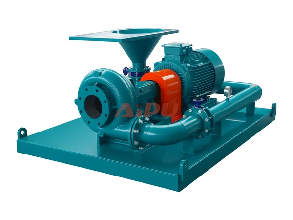
3. The Jet Mixer Head: Anatomy of the Device
The jet mixer head itself consists of several precisely engineered components:
The Nozzle:
-
A tapered converging section that narrows to a small orifice
-
Converts pressure energy to velocity energy
-
Creates the high-velocity jet that drives the entire process
-
Typically designed for specific flow rates and pressures
The Suction Chamber:
-
The area surrounding the nozzle exit
-
Connected to the hopper via the pickup tube
-
Where the vacuum draws in powder
-
Designed to optimize powder entrainment
The Throat:
-
The narrowest section where maximum velocity occurs
-
Where intense mixing begins as powder meets high-velocity fluid
-
Carefully sized for the expected flow rate
The Diffuser:
-
A tapered expanding section following the throat
-
Gradually converts velocity back to pressure
-
Completes the initial mixing process
-
Discharges to the tank return line
The Hopper Connection:
-
Pickup tube connects hopper base to suction chamber
-
Butterfly valve controls powder flow
-
Screen may be present to prevent lumps from entering
4. Step-by-Step Operating Sequence
Step 1: Establish Base Flow
The centrifugal pump starts, drawing fluid from the mud tank and delivering it to the jet mixer inlet at controlled pressure (0.22-0.4 MPa). This fluid is typically:
-
Water for preparing new mud
-
Base mud for weighting operations
-
Treated fluid for chemical additions
Step 2: Acceleration Through the Nozzle
As the fluid enters the nozzle, it encounters the tapered constriction. To maintain mass flow, velocity increases dramatically—often to 20-30 meters per second or more. According to Bernoulli's principle, this velocity increase comes at the expense of pressure.
Step 3: Vacuum Creation
At the nozzle exit, fluid pressure has dropped below atmospheric pressure. This creates a vacuum in the suction chamber that communicates through the pickup tube to the hopper above.
Step 4: Powder Entrainment
The vacuum draws air and dry powder from the hopper down through the pickup tube. At the bottom, the powder enters the suction chamber where it meets the high-velocity fluid jet.
Step 5: Initial Mixing in the Throat
The fluid jet, now traveling at maximum velocity, impacts the incoming powder stream in the throat section. The high turbulence and velocity differential cause:
-
Powder particles to be torn apart
-
Initial wetting of particle surfaces
-
Formation of a concentrated slurry
Step 6: Pressure Recovery in the Diffuser
As the mixture enters the expanding diffuser section, velocity decreases and pressure recovers. This pressure recovery:
-
Completes the initial mixing
-
Prevents cavitation in downstream piping
-
Provides energy to return the mixture to the tank
Step 7: Discharge to Tank
The mixed slurry exits the diffuser and flows through the discharge line back to the mud tank, typically directed:
-
Into an agitated compartment
-
Away from pump suction to allow hydration time
-
Often aimed to enhance tank circulation
Step 8: Final Mixing in the Tank
The jet mixer alone does not complete the mixing process. Tank agitators and mud guns work continuously to:
-
Maintain solids suspension
-
Complete hydration of bentonite
-
Ensure uniform density throughout the tank
-
Prevent settling of heavy materials like barite
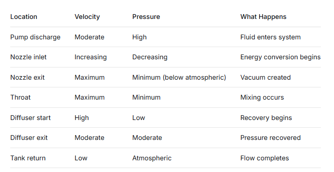
5. The Pressure-Velocity Relationship
Understanding what happens to pressure and velocity at each point helps explain why the mixer works:
6. The Powder Pickup Mechanism
The powder pickup process involves more than simple suction:
Air Entrainment:
The vacuum draws not only powder but also air from the hopper. This air:
-
Helps fluidize the powder, making it flow like a liquid
-
Prevents bridging in the pickup tube
-
Is eventually separated in the tank
Powder Flow:
Dry powder behaves almost like a fluid when aerated. The air drawn with it:
-
Reduces friction in the pickup tube
-
Maintains continuous flow
-
Prevents plugging
Wetting Process:
As powder enters the high-velocity fluid jet:
-
Surface wetting begins almost instantly
-
High turbulence strips away any coating that would slow hydration
-
Particles are dispersed throughout the fluid
7. Hydraulic Calculations
For a typical jet mixer operating at design conditions:
Given:
-
Inlet pressure: 0.22-0.4 MPa (32-58 psi)
-
Flow rate: 150-200 m³/h (660-880 gpm)
-
Pipe diameter: 6" (150 mm)
At the nozzle:
-
Velocity increases by factor of 10-20×
-
Pressure drops to -0.05 to -0.1 MPa gauge (vacuum)
Resulting suction:
-
Can lift powder several meters vertically
-
Bentonite pickup: 180 kg/min (400 lb/min)
-
Barite pickup: 315 kg/min (700 lb/min)
8. The Role of the Butterfly Valve
The butterfly valve between hopper and pickup tube is more important than it might seem:
Control Function:
-
Regulates powder flow rate
-
Prevents flooding (adding powder faster than it can be wetted)
-
Allows instant shutoff when target properties reached
Proper Operation:
-
Valve should be opened gradually, not fully at once
-
"Feel" for the point where hopper begins to empty steadily
-
Adjust to maintain continuous powder flow without plugging
Signs of Improper Adjustment:
-
Valve too far open: Hopper empties too fast, plugging occurs
-
Valve too far closed: Slow addition, inefficient operation
-
Fluctuating flow: Indicates bridging in hopper or pickup tube
9. What Happens to the Powder
Following a single bentonite particle through the mixer illustrates the process:
-
In hopper: Particle rests among thousands of others, aerated by incoming air
-
Entering pickup tube: Particle begins moving downward with air flow
-
Entering suction chamber: Particle meets high-velocity fluid jet
-
Impact: Particle is immediately surrounded by fluid
-
In throat: High turbulence begins tearing apart the particle agglomerate
-
Wetting begins: Water penetrates particle surface
-
In diffuser: Continuing turbulence further disperses
-
In tank: Particle continues hydrating over hours
-
Final state: Fully hydrated clay platelet contributing to viscosity
10. Why Barite and Bentonite Behave Differently
The same mixer handles both materials, but they behave differently:
Bentonite:
-
Low density (~2.6 specific gravity)
-
Flows easily when aerated
-
Hydrates and swells
-
Maximum rate: ~180 kg/min
Barite:
-
High density (~4.2 specific gravity)
-
Tends to settle quickly in air
-
Abrasive, can wear equipment
-
No hydration, just suspension
-
Maximum rate: ~315 kg/min (higher because no hydration limit)
Reason for difference:
Barite's higher density means more mass flows through the same opening, and since it doesn't hydrate, there's no risk of swelling and plugging.
11. Operating Parameters That Affect Performance
Inlet Pressure:
-
Too low: Insufficient vacuum, poor powder pickup
-
Too high: Excessive velocity, unnecessary wear, potential cavitation
-
Optimal: 0.22-0.4 MPa (within manufacturer specifications)
Fluid Properties:
-
Viscosity: Higher viscosity reduces pickup efficiency
-
Density: Heavier base fluid requires more energy
-
Temperature: Affects viscosity and vapor pressure
Powder Condition:
-
Dry, free-flowing powder works best
-
Lumps or moisture cause plugging
-
Fluidized powder (aerated) flows better
12. Visual Indicators of Proper Operation
Experienced operators learn to read the mixer:
Good Operation:
-
Steady flow of powder from hopper
-
Consistent sound of material flowing
-
No surging or sputtering
-
Tank level rises as expected
-
Mud properties change predictably
Problems:
-
Hopper vibrates but powder doesn't flow: Bridging
-
Sputtering discharge: Flooding or plugging
-
High-pitched whistle: Nozzle worn or damaged
-
Pump pressure fluctuating: Suction problems
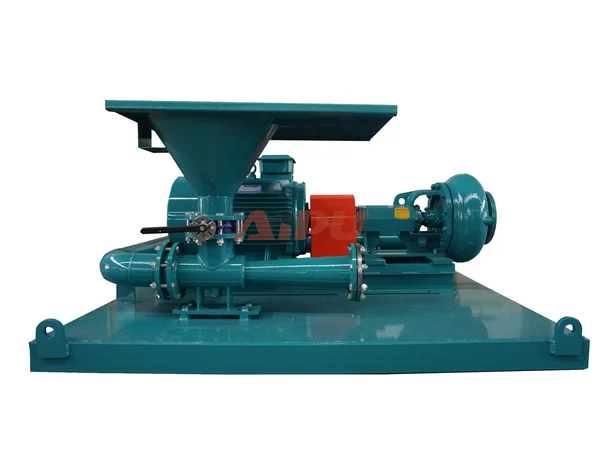
13. The Portable Jet Mixer
The portable version operates on exactly the same principle but with added flexibility:
Design Differences:
-
Frame-mounted for mobility
-
Quick-connect hose fittings
-
May include its own small tank
-
Often lighter construction
Operation:
Same sequence but with:
-
Hoses connected to pump and tank
-
Often positioned at tank edge
-
Can be moved between tanks as needed
14. Common Operating Mistakes
Adding Powder Too Fast:
The most common error. When powder enters faster than the fluid can wet it:
-
Plugging occurs in throat or discharge
-
Unwetted powder accumulates
-
Flow stops until cleared
Starting Without Flow:
Opening the butterfly valve before pump is running and flow established:
-
Powder drops into dry mixer
-
Creates plug that blocks flow when pump starts
-
Requires disassembly to clear
Ignoring Vacuum Gauge:
If equipped, vacuum gauge provides valuable information:
-
Low vacuum: Pump problem, suction leak, worn nozzle
-
High vacuum: Plugging, flow restriction
Neglecting Screen:
Screen in hopper prevents lumps from entering:
-
If missing, lumps plug pickup tube
-
If plugged, powder flow stops
15. Integration with Tank Agitation
The jet mixer does not complete the mixing job alone. Proper tank agitation is essential:
Immediately After Addition:
-
Agitators prevent settling of heavy materials
-
Begin distributing material throughout tank
During Hydration:
-
Bentonite requires hours to fully hydrate
-
Gentle agitation maintains suspension without shearing gel structure
-
Over-agitation can degrade viscosity
For Barite:
-
Continuous agitation essential to keep weighted material suspended
-
Settled barite can pack hard, requiring cleaning
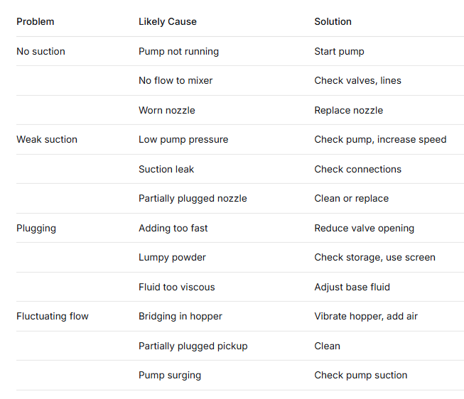
16. Troubleshooting Guide
17. The Physics Summary
In essence, the jet mud mixer works through a brilliant application of basic physics:
-
Pressure energy from the pump is converted to velocity energy in the nozzle
-
High velocity creates low pressure (vacuum) that draws in powder
-
Turbulence in the throat mixes powder and fluid
-
Pressure recovery in the diffuser returns energy to move the mixture
-
Tank agitation completes the process
No motors, no moving parts in the mixing head—just fluid dynamics doing the work.
Conclusion
The jet mud mixer works by harnessing one of fluid mechanics' most elegant principles: the venturi effect. A simple tapered nozzle converts pump pressure into high velocity, which creates vacuum that draws dry powder into the fluid stream. Turbulence in the throat mixes powder and fluid, while the diffuser recovers pressure to return the mixture to the tank.
This elegantly simple design—with no moving parts in the mixing head itself—has made the jet mixer the universal standard for drilling fluid preparation for decades. It rapidly incorporates bentonite at 180 kg/min for spud mud, adds barite at 315 kg/min for weighting operations, and handles a wide range of chemical treatments. While it cannot match the shear intensity of dedicated shearing pumps for polymer hydration, for bulk material incorporation and routine maintenance, the venturi-powered jet mixer remains the workhorse of every drilling fluid system.
Related Products