What is a Solids Control System? The Complete Guide to Drilling Fluid Management
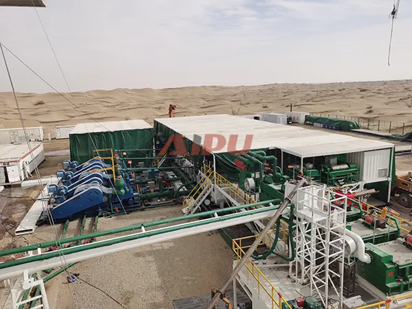
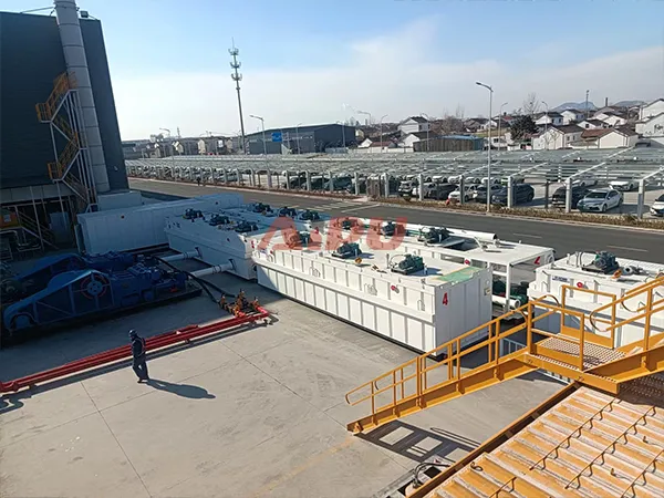
After exploring each individual component—shale shakers, desanders, desilters, centrifuges, degassers, agitators, pumps, and tanks—it's time to understand how all these elements work together as an integrated system. A solids control system is not merely a collection of equipment; it is a carefully engineered process designed to maintain drilling fluid properties, protect downhole equipment, ensure drilling efficiency, and comply with environmental regulations.
1. Definition and Core Concept
A solids control system is an integrated arrangement of mechanical equipment designed to process drilling fluid (mud) by removing drilled solids (cuttings) and maintaining optimal fluid properties for continued use in the drilling operation.
The Fundamental Principle:
Drilling fluid circulates continuously during operations:
-
Pumped down the drill string
-
Exits through bit nozzles to clean and cool the bit
-
Carries cuttings up the annulus to surface
-
Returns to surface with entrained solids
-
Processed by solids control equipment to remove solids
-
Returns to suction pit for recirculation
Without effective solids control, each cycle would add more drilled solids to the fluid, progressively degrading its properties until it becomes unusable—requiring expensive dilution or disposal.
2. Why Solids Control Matters
The Economic Imperative:
Drilling fluid is expensive—often costing hundreds of thousands of dollars per well. Barite, polymers, and other additives represent significant investment. A good solids control system:
-
Extends mud life, reducing replacement costs
-
Reduces barite consumption through recovery
-
Minimizes dilution requirements
-
Lowers waste disposal volumes and costs
The Operational Imperative:
Poor solids control leads to:
-
Increased torque and drag
-
Reduced rate of penetration (ROP)
-
Differential sticking
-
Formation damage
-
Lost circulation
-
Excessive equipment wear
-
Well control complications
The Environmental Imperative:
Solids control reduces:
-
Volume of waste requiring disposal
-
Environmental footprint of drilling operations
-
Transportation costs for waste removal
-
Liability from improper disposal
3. The Stages of Solids Control
The industry standard recognizes a four-stage mechanical solids control process, with additional specialized equipment for specific functions:
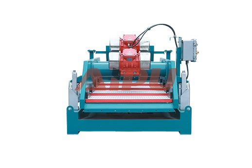
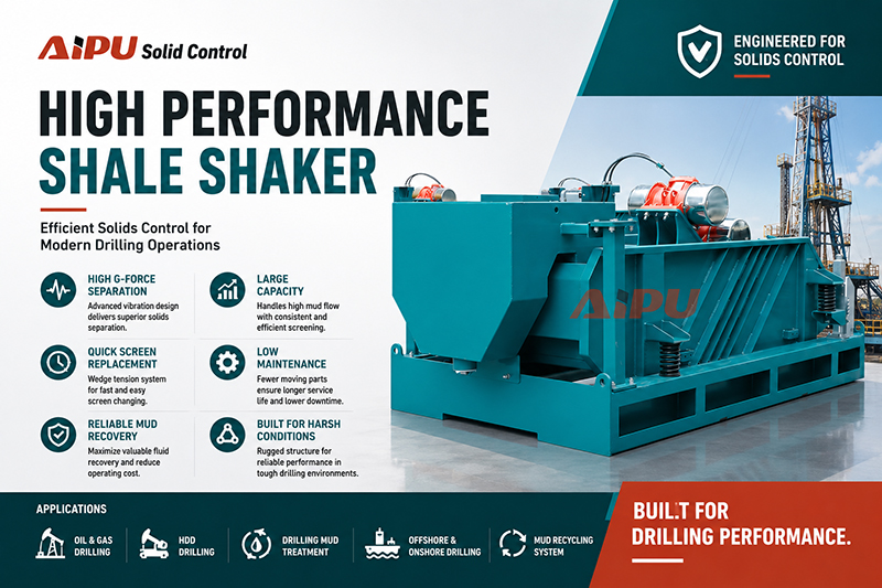
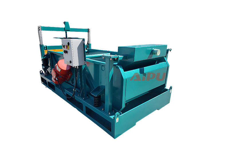
Stage 1: Shale Shakers (Primary Separation)
-
Equipment: Linear motion or balanced elliptical shakers (Hunter-MG series)
-
Function: Remove large cuttings (>74 microns)
-
Position: First equipment receiving returns from well
-
How It Works: Vibrating screens separate coarse solids; liquid and fine solids pass through
-
Key Specifications:
-
Screen area: 1.35-8.1 m² depending on model
-
Capacity: 50-420 m³/h
-
G-force: 6.0-7.0G
-
Multiple deck angle options for optimization
-
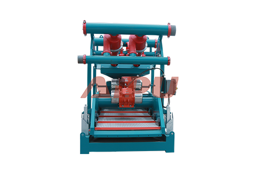
Stage 2: Desanders (Second Stage)
-
Equipment: Hydrocyclone banks (APCS series, Hunter S series)
-
Function: Remove sand-sized particles (44-74 microns)
-
Position: After shakers, before desilters
-
How It Works: Centrifugal force in 10" cones separates medium solids
-
Key Specifications:
-
Cones: 8" or 10" diameter
-
Capacity: 60-360 m³/h
-
Separation point: 44-74 μm
-
Working pressure: 0.25-0.45 MPa
-
Optional bottom shaker for underflow drying
-
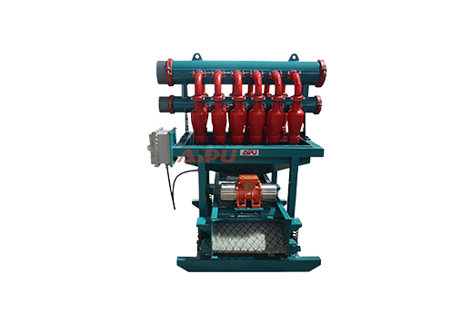
Stage 3: Desilters (Third Stage)
-
Equipment: Small hydrocyclone banks (APCN series, Hunter N series)
-
Function: Remove fine particles (15-44 microns)
-
Position: After desanders, before centrifuges
-
How It Works: Higher G-forces in 4" cones separate finer solids
-
Key Specifications:
-
Cones: 4" diameter (100% polyurethane)
-
Capacity: 60-360 m³/h
-
Separation point: 15-44 μm
-
Clamp-type connections for easy maintenance
-
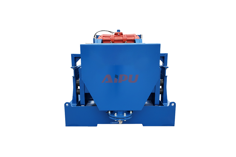
Stage 4: Centrifuges (Fourth Stage)
-
Equipment: Decanter centrifuges (APLW series, APLWS series)
-
Function: Remove ultra-fine particles (2-7 microns) or recover barite
-
Position: Final mechanical processing stage
-
How It Works: High-speed rotation (up to 3200 rpm) creates G-forces exceeding 2000G
-
Key Specifications:
-
Drum diameter: 355-600 mm
-
Capacity: 35-65 m³/h
-
Separation point: 2-7 μm (depending on model)
-
Separation factor: 755-2435G
-
Three-phase models available for oil/water/solids separation
-
Specialized Equipment:
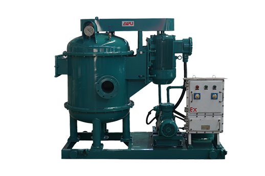
Degassers (Gas Removal)
-
Equipment: Vacuum degassers (APZCQ, APLCQ, APVD series)
-
Function: Remove entrained gas (methane, H₂S, CO₂)
-
Position: After shakers, before desanders
-
Key Specifications:
-
Capacity: 240-360 m³/h
-
Efficiency: ≥95%
-
Vacuum degree: -0.02 to -0.04 MPa
-
H₂S-resistant steel option for sour service
-
Mud Agitators (Suspension Maintenance)
-
Equipment: Gear-driven agitators (APMA series)
-
Function: Keep solids suspended, maintain homogeneous mixture
-
Position: Mounted on tanks throughout system
-
Key Specifications:
-
Motor power: 5.5-15 kW
-
Impeller speed: 60-72 rpm
-
Single or dual impeller configurations
-
Shaft length customized for tank depth
-
Mud Tanks (Infrastructure)
-
Equipment: Compartmentalized steel tanks
-
Function: Hold fluid, support equipment, provide flow paths
-
Features:
-
Sloped or V-shaped bottoms for cleaning
-
Multiple compartments for sequential processing
-
Baffle systems for controlled flow
-
Marine-grade corrosion protection
-
Transfer and Feeding Equipment:
Centrifugal Pumps (APSB series)
-
Move fluid between tanks and to equipment
-
Flow rates: 45-255 m³/h
-
Heads: 16-32 m
-
Power: 7.5-75 kW
Single Screw Pumps (APG series)
-
Centrifuge feed pumps
-
Stable, pulse-free flow
-
Power: 2.2-18.5 kW
Submersible Slurry Pumps (APYZ series)
-
For tank cleaning and transfer
-
Flow rates: 30-270 m³/h
Mud Mixing Equipment:
Jet Mud Mixers (APSLH series)
-
Add bulk materials (bentonite, barite)
-
Venturi principle creates suction
-
Capacity: 150-200 m³/h flow, 180 kg/min bentonite, 315 kg/min barite
-
Inlet pressure: 0.22-0.4 MPa
Shearing Pumps (APJQB series)
-
High-energy mixing for polymers
-
Accelerate hydration, eliminate fish eyes
-
Save 30%+ on bentonite
-
Power: 37-55 kW, Speed: 1900-2200 rpm
4. The Flow Path: How Fluid Moves Through the System
Understanding the sequence is essential:
Step 1: Returns from Well
Gas-cut, solids-laden mud returns from the wellbore, typically at 40-70°C, and enters the first tank compartment.
Step 2: Shale Shakers
Mud flows over shaker screens. Large cuttings (>74 μm) are removed and discharged to cuttings boxes. Screened mud falls into the sand trap compartment below.
Step 3: Degassing (if required)
If gas is present, mud flows to the degasser. Vacuum removes entrained gas, which is vented to a flare. Degassed mud returns to the tank.
Step 4: Desander Processing
Mud is pumped to desander hydrocyclones (10" cones). Sand-sized solids (44-74 μm) are removed as underflow. Cleaned mud returns to the next compartment.
Step 5: Desilter Processing
Mud is pumped to desilter hydrocyclones (4" cones). Fine solids (15-44 μm) are removed. Underflow may go to a bottom shaker for further dewatering.
Step 6: Centrifuge Processing
For ultra-fine control or barite recovery, mud is fed to decanter centrifuges. Solids (2-7 μm) are removed as dry cake; liquid returns to system.
Step 7: Suction to Mud Pumps
Clean, conditioned mud reaches the suction compartment, where mud pumps draw it for recirculation downhole.
Throughout the Process:
-
Agitators run continuously, keeping solids suspended
-
Mud guns assist in cleaning and circulation
-
Transfer pumps move fluid between compartments as needed
-
Mixers add new materials to maintain properties
5. Types of Solids Control Systems
By Rig Size and Complexity:
Small Land Rigs:
-
Single tank with 2-3 compartments
-
Shale shaker + desander + desilter (often combined as mud cleaner)
-
Basic agitators
-
Capacity: 50-150 m³/h
Medium Land Rigs:
-
2-3 tank system
-
Full 4-stage processing
-
Degasser included
-
Centrifuge for weighted/unweighted muds
-
Capacity: 150-300 m³/h
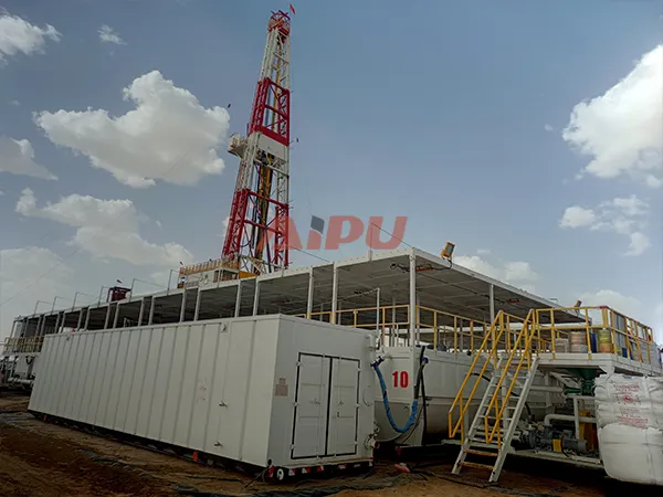
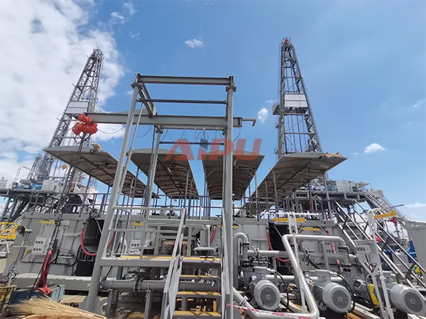
Large Land Rigs / Offshore Rigs:
-
Multiple large tanks (4-6)
-
Full 4-stage with redundancy
-
Multiple centrifuges
-
Advanced degassing
-
Complete mixing and shearing systems
-
Capacity: 300-600+ m³/h
By Application:
Standard Drilling Systems:
-
Conventional oil/gas wells
-
Four-stage processing typical
High-Performance Systems:
-
Extended reach, deep water, high-temperature wells
-
Enhanced centrifuge capacity
-
Advanced polymer shearing
CBM (Coal Bed Methane) Systems:
-
Focus on fine solids removal
-
Environmental compliance emphasis
H₂S Sour Service Systems:
-
Special materials throughout
-
Enhanced gas handling
-
Rigorous safety systems
6. Integration with Waste Management
Modern solids control systems integrate with waste management:
Cuttings Handling:
-
Shaker discharges to cuttings boxes or screw conveyors
-
Centrifuge discharges to cuttings dryer or direct to skip
Dewatering:
-
Centrifuge underflow further dewatered
-
Filter presses for final solids drying (moisture ≤15%)
Oil Recovery:
-
Three-phase centrifuges recover base oil
-
Oil returned to mud system, reducing purchases
Water Treatment:
-
Clarified water reused or treated for discharge
7. System Design Considerations
Flow Rate Matching:
All equipment must be sized for the rig's maximum circulating rate. A bottleneck anywhere reduces system effectiveness.
Tank Capacity:
Sufficient volume for:
-
Retention time (solids settling, chemical reactions)
-
Reserve mud storage
-
Emergency capacity (kick situations)
-
Equipment suction requirements
Head Requirements:
Pumps must provide adequate pressure for:
-
Hydrocyclone feed (0.25-0.45 MPa)
-
Jet mixer operation (0.22-0.4 MPa)
-
Transfer distances
Redundancy:
Critical systems often include backup equipment:
-
Dual shakers
-
Standby pumps
-
Spare centrifuges for weighted/unweighted service
Hazardous Area Classification:
Electrical equipment must meet:
-
ATEX, IECEX certifications where required
-
Explosion-proof ratings
-
Appropriate temperature classifications
8. Key Performance Indicators
Solids Removal Efficiency:
-
Shakers: Remove >74 μm
-
Desander: Remove 44-74 μm (typically 50-70% of incoming solids in this range)
-
Desilter: Remove 15-44 μm (40-60% efficiency)
-
Centrifuge: Remove 2-7 μm (removes fine particles, recovers barite)
Mud Property Maintenance:
-
Density control within ±0.1 ppg
-
Viscosity within range
-
Sand content <0.5% (API spec)
-
MBT (Methylene Blue Test) within limits
Economic Metrics:
-
Dilution rate (barrels of new mud per foot drilled)
-
Barite consumption
-
Waste volume per foot drilled
-
Screen life
9. Common Configurations
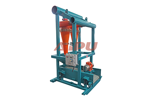
Mud Cleaner Configuration:
Combines desander and desilter cones over a small shaker:
-
Hunter S series: 10" desander cones + shaker
-
Hunter N series: 4" desilter cones + shaker
-
Benefits: Dewaters underflow, recovers liquid
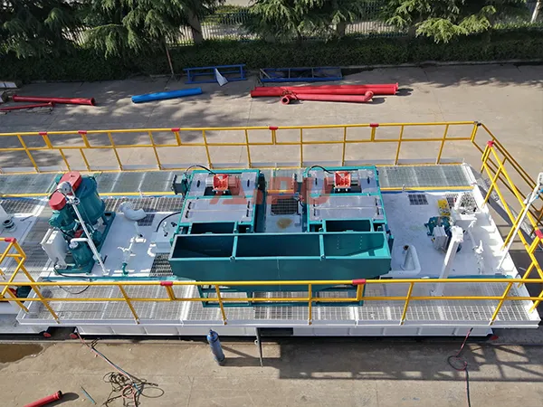
Compact Systems:
Hunter-Mini, Hunter-MG series for smaller rigs:
-
Smaller footprint
-
Lower capacity
-
Simplified operation
Modular Systems:
Individual tank modules that connect:
-
Flexible arrangement
-
Easy transport
-
Scalable for different rig sizes
10. Auxiliary Systems
Mud Gas Separator (APMGS series):
-
Separates large gas volumes before degasser
-
Vessel diameter: 800-1400 mm
-
Capacity: 200-420 m³/h
-
H₂S-resistant option
Flare Ignition Systems (APFI series):
-
Burns vented gas
-
Remote control operation
-
Vertical/horizontal configurations
Auger Feeders (APLS series):
-
Transfer cuttings to collection points
-
Power: 5.5-15 kW
-
Customizable length and diameter
Vacuum Transfer Pumps (APVTP series):
-
Handle high-solids materials
-
80% solids capability
-
Suction distance: 50m, discharge: 1000m
11. Environmental and Economic Benefits
Reduced Waste:
-
Effective solids control reduces waste volume by 50-70%
-
Lower disposal costs
-
Extended mud life reduces new material purchases
Barite Recovery:
-
Centrifuges recover 85-95% of barite
-
Reduces barite purchases by 30-50%
-
Significant cost savings in weighted mud systems
Chemical Savings:
-
Shearing pumps reduce polymer/bentonite use by 30%+
-
Cleaner mud requires less chemical treatment
-
Longer mud life reduces additive consumption
Reduced NPT:
-
Fewer equipment failures
-
Less stuck pipe
-
Better hole conditions
-
Faster ROP
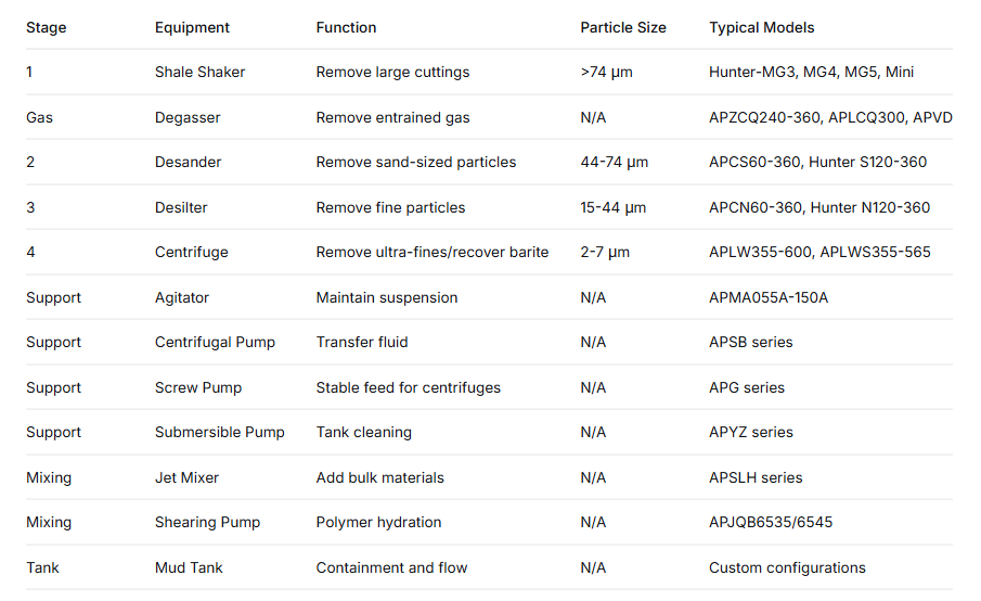
12. The Complete Picture: Equipment Summary Table
13. Conclusion
A solids control system is the circulatory system of the drilling operation. Just as the human body requires clean blood to function, a drilling rig requires clean mud to operate efficiently and safely. Each component plays a specific role:
-
Shale shakers are the first line of defense, removing the largest cuttings
-
Degassers eliminate the invisible threat of entrained gas
-
Desanders and desilters progressively remove smaller and smaller solids
-
Centrifuges provide the final polish, removing ultra-fines or recovering valuable barite
-
Agitators keep everything in suspension
-
Tanks provide the infrastructure
-
Pumps move fluid through the system
-
Mixers maintain and adjust mud properties
When all these components work together in proper sequence, the result is:
-
Consistent, predictable mud properties
-
Efficient drilling with fewer problems
-
Extended equipment life
-
Reduced environmental impact
-
Lower overall drilling costs
The solids control system transforms drilling fluid from a costly consumable into a reusable asset, enabling the modern drilling industry to operate safely, efficiently, and responsibly.
Related Products